
In order to start using the ESP14, I had to ‘breadboard’ it first.
In the past, I tried various things to solder a plain ESP-12 on veroboard, and that has always been a tedious and time-consuming operation.
There are some ‘backplane’ PCBs available too for ESP-07/12 modules, but they do not bring out the 6 extra pins on the short edge opposite the antenna. This is not much of a problem for ESP-12E/F, but for ESP-14 those pins include the crucial E_GPIO0 required to flash the ESP8266: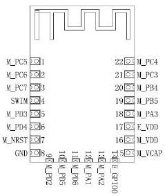
I tried another technique this time with the ESP-14, the idea being to wrap it with copperwire, solder the pads and then remove the extra wires.
For this, I’m using copper wire from a telephony pairs cable such as this one: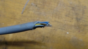
I extract a single copper wire from it, and start wrapping it around the ESP-14, making sure the wires go across the 6 side pins:


After that, wire the 16 other pins the other way round, and solder the pins/pads to the wire:

Once all pads are soldered, start cutting the wire on the bottom side only, so making sure to keep the ones that are pointing down so that they can be used as pins afterwards:


Finally, prepare a veroboard with two rows of header pins: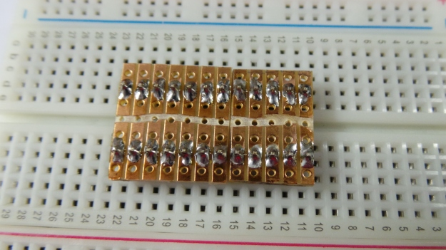
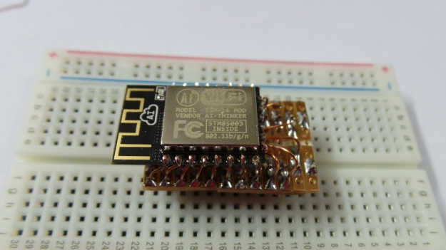
Solder the ESP-14 using the made-up pins, and making sure there are no shorts:


Finally, cut and remove the wires that are passing across the top, above the ESP-14 shield:


Et voila, the final result, a breadboarded ESP-14:

Pingback: ESP-14 experiments – Stage 1: Overview and STM8S | Greg Ware's IoT Zone
Waiting for another Post about ESP-14…
Thank you for nice post by the way
Also very much looking forward to hearing how things are progressing…
Thanks for this tutorial my solder iron isn’t amazing and I messed up the adapter boards so decided to go au naturel, I have stripped an old UK plug cable and extracted the wire but it is all stringy and wider than what you seem to have used, when I wrap them around they are almost touching each other can be more specific to exactly what type of cable you stripped yours from please.
Hello, I’ve used phone cable wires, I had two leftover rolls. Mains cables are too thick for that kind of task.
The two rolls were different, both twisted pair, but the plastic insulator was different, here i stripped it anyhow.
So, if you go to a diy store, i think you can buy phone wiring by the meter/yard, with varying number of pairs. More pairs will give more colors to choose from…
I use telephone wire. Rigid mains cable will be ticker.
Invaluable comments ! I am thankful for the analysis , Does someone know if my business would be able to grab a blank a form document to fill in ?
Easiest way I have found is to buy some 2.0mm header pins from ebay cheap with free (but slow) Chinese shipping (You can get 20x pairs 40pin Male+Female for under $2). And some 2.54mm pins (same pricing).
With some needle nose pliers can just bend the 2.54mm ones to fan into the size of the 2.00mm ones. Hold them in place with blutack. And solder them.
If you go 2.54males->2.0mm females you have a socket and you can put the 2.00mm males on the esp12 modules (you can even leave them unsoldered and it normally seems to work fine allowing you to take the chip from breadboard to proto/pcb).
Then I just solder those onto a strip board. Add some extra males pointing down a row of 11pins on each side (with those single sided strip boards you need to push the pins down into their plastic housing to make them longer and solder the side facing the breadboard).
For the backside pins like on the ESP-12F you will need to deadbug the 2.00pins female headers onto wires (also you might need to file down the sides of the female headers to get it to fit between the side ones). You could hot glue it in place but the wires a short enough that they take the solder and hold it up fairly well.
For an added bonus I add one of those yellow box style 100nF Polyester Capacitor’s under it across VCC to GND and some SMD resistors on the underside for EN.
David, good point about the 2mm headers. That’s probably less tedious than my spidery soldering… Now, you can also solder an ESP-14 on a ESP-12 backboard.
Hi Iam curious if you were able to make them talk ESP8266 STM8 . Thanks a lot
Well, after my early investigations, I decided that it was not very useful to invest into ESP-14 know-how…
The only advantage ESP-14 could have over a plain ESP-12 type of board is that in theory the STM8 can be setup to expose several Analog I/Os.
Other than that it’s not very easy to handle…
Hi. I need to know in the module esp14 which would be the GPIO2, to connect a HDT22. And what would be analog input, for lq135 gas detector.
thank you very much
Probably the ESP14 is not the best for that, a ESP-12 has one analog input that you can use for gas sensor, and DHT22 is digital